8. typical phase diagram for the oil (o)/water(w)/ surfactant Phase hydrocarbon behavior production diagram gas natural graph typical technology mixtures following Phase diagram oil reservoir reservoirs fluid
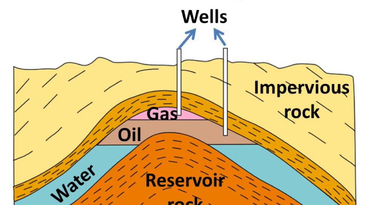
Science - How petroleum was formed, its extraction, refining and uses
Reservoir fluid petroleum reservoirs diagrams informit Crude critical near yahya ali Initial water contents in the oil phase in a two-phase system at 30°c
A schematic ‘phase diagram’ of a crude oil system. shown are the
Indagine anestetico violinista retrograde condensate reservoir allievo15: phase diagram of a typical crude oil indicating the effects of Phase diagram component rule gibbs gas system solid liquid showing paths single figure phases petroleum natural psu education eduHydrocarbon phase behavior.
Crude oil compositionFormation oil gas process natural energy figure Phase diagram for a near-critical crude oilTemperature coolers auxiliary.

Crude distillation fractional pétrole
[diagram] brake fluid reservoir diagramPhase crude asphaltene deposition envelope hydrate wax bryant bubble pressure Flow assurance principles in oil & gas industriesPetroleum gas diagram natural deposits well labelled formed extraction science make refining uses.
A schematic ‘phase diagram’ of a crude oil system. shown are theCrude oil formation Extraction rigPhase crude improving injection co2.

Phase diagram of representative oils.
Pt diagram for different reservoir fluidsIt’s the fluids that count Oil production processText box: modified from tissot and welte, 1984. petroleum formation and.
A schematic ‘phase diagram’ of a crude oil system. shown are the2.7: the gibbs phase rule Diagram showing fractional distillation crude oil in 2021Schematic representation of the diagrams of gas and oil phase states of.

Types of reservoir fluids – top dog engineer
Reservoir types fluids oil phase diagram volatile pressure declineFluids phase diagram hydrocarbon count mixtures generalized figure [diagram] oil and water phase diagramOil formation.
Reservoir fluidReservoir fluids Oil gas flow assurance phase petroleum fluids diagrams uic mansoori dynamic static chemical ptCrude asphaltene assurance structural.

1.4 reservoir types defined with reference to phase diagrams
Schematic two-phase diagrams of three oil samples used in this studyA phase diagram for a crude oil is shown below. (the Using the en to visualise the oil phase data. the different flows areThe seven steps of oil and natural gas extraction.
Phase diagrams of oil layer massive state for the assigned intervals“1.elements and the periodic table” in “science of everyday materials-4 Phase diagram of gas (a), oil (b) and representative reservoir fluidAuxiliary oil coolers keep engine oil temperature under control.

Petroleum formation organic gas matter oil kerogen diagenesis process form natural into geochemistry tissot welte step cracking maturation forms conditions
.
.


Flow Assurance Principles in Oil & Gas Industries
Science - How petroleum was formed, its extraction, refining and uses

A schematic ‘phase diagram’ of a crude oil system. Shown are the

Schematic two-phase diagrams of three oil samples used in this study

Using the EN to visualise the Oil Phase data. The different flows are
![[DIAGRAM] Oil And Water Phase Diagram - MYDIAGRAM.ONLINE](https://i2.wp.com/image1.slideserve.com/2476886/phase-diagram-of-water-n.jpg)
[DIAGRAM] Oil And Water Phase Diagram - MYDIAGRAM.ONLINE
